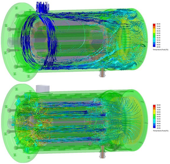
Air cooling of a reluctance motor

As an example for the simulation of air-cooled components, the air cooling of a reluctance motor, which was designed within the HyFly research project, is displayed here. CHT simulations serve to secure the design. The special requirements in this project resulted from the compactness of the designed propulsion unit consisting of gas turbine, reluctance motor and gear unit. The cooling air flow provided in the front part of the unit is directed through an inlet opening into the double-walled casing jacket and flows from there to the rear part of the casing. This ensures that the airflow is used optimally by additionally cooling the outer casing jacket instead of being guided directly past the engine combustion chamber, which would heat it unnecessarily. At the front end the flow is deflected by 180°, and inside the motor, the flow is guided in the opposite direction along the electrical components to be cooled. There are openings in the locating bearing cover through which the heated air flow is discharged to the outside into the environment. By means of iterative casing geometry optimisation, sufficient cooling of the reluctance motor could be guaranteed.